Product Description
Zephyr Power Vent
Battery Box Ventilator & Back Draft Damper
 12/24V Model |  48V Model |
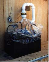 Simple installation with plastic hood to pipe gas into Power Vent | |
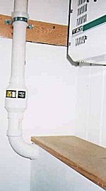 Installation with battery box. | |
|
12 & 24 VOLT 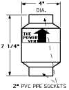 | |
|
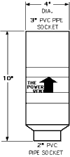 | |
Why use a POWER VENT?
- Positive venting of hydrogen gas.
- Stops back drafting.
- Puts the smell outside.
- Keeps batteries warmer in cold climates.
- Uses very little power.
- Excellent results for over four year
The Zephyr POWER VENT was designed for use in remote home power systems. The concept arose from field experience of systems with enclosed battery boxes. Quite often the NEC required venting was found back drafting, thus cooling the battery bank and lowering its' capacity as well as venting hydrogen gas into the structure.
The POWER VENT alleviates this condition by keeping a gravity operated damper closed within the vent pipe except at times when the batteries are being charged and producing hydrogen gas. During these times the battery box is force vented with a low power, sparkless fan which overcomes the damper sending the gas outdoors. The "fan on" mode is determined by the battery voltage. When the batteries are "gassing" during charge periods the battery voltage will read above normal. A voltage sensitive switch is required in the system to make the on/off determination. All TRACE SW model inverters have a programmable auxiliary relay which can operate the POWER VENT. Other systems require the addition of a voltage controlled switch.
The POWER VENT is designed around typical home power systems with battery banks under 2,200 amp hours and charge rates under 150 dc amperes. Systems larger than this can produce more hydrogen gas than the expel rate of the POWER VENT which operates in the 5 to 8 cubic foot per minute range. Two vents may be used for higher volume.
Comes in 3 voltages: 12, 24 and 48 Volts DC
SPECIFICATIONS
| 12 AND 24 VOLT | 48 VOLT |
| Shipping Weight: 3 Lbs. | Shipping Weight: 4 Lbs. |
| Size: 4" Dia. x 7.25" | Size: 4" Dia. x 10" |
| Power consumption: 3 watts or less | Power consumption: 6 watts or less |
| Voltage: 12 or 24 VDC | Voltage: 48 VDC |
| Air volume: 6 cfm with 360° maximum change of direction | Air volume: 8 cfm with 360° maximum change of direction |
POWER VENT FAQ's
Q. What is "hysteresis"?
A. The difference between the relay activation and deactivation.
Other Questions
Q. Can I stack two Power Vents in a row to move more air?
A. No. If you need to move more air you can use two vents, but each one must have its' own vent pipe. You could combine the two exhausts into one larger vent. i.e. combine two 24 volt Power Vents with 2" outputs into one 3" vent pipe using an inverted wye.
Q. Is the Power Vent Explosion proof rated?
A. There is no explosion proof rating on the Power Vent. The fans are brushless dc motors using electronics to switch the fields without arcing. The cost of an explosion proof rating is prohibitive.
INSTALLATION DIAGRAMS
POWER VENT INSTRUCTIONS
The POWER VENT must be placed vertically with the label right side up in order for the backdraft damper to function properly. Place the POWER VENT higher than the top of the battery box and indoors, especially in cold climates. Use no more than four 90° bends including one at the exterior terminus facing down. Put a screen on the outside pipe terminus to keep insects and debris out. Use 2" PVC dwv pipe on 12 and 24 volt systems. Use 2" intake and 3" output PVC dwv pipe on 48 volt systems.
Place a 1 amp fuse (included) at the start of the positive circuit wire. A controller is usually used in the circuit to cycle the fan . Either an auxiliary relay in the Trace SW series inverter or a Solar Converters Simple Switch may be used. Refer to the appropriate manual for hook up and programming instructions. The voltage set points for turning the fan on and off are above the full state of charge voltage of the battery but below the battery gassing voltage. In the case of grid tied systems where the batteries are kept at float voltage 24 hours/day it may be necessary to run the fan full time as the batteries are always gassing.
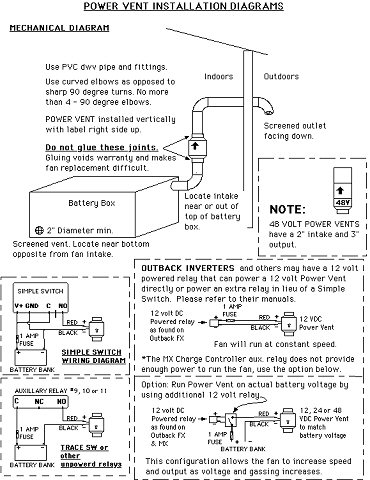
A controller is usually used in the circuit to cycle the fan. OutBack inverters and charge controllers may have a 12 volt powered auxiliary relay available. Other inverters may or may not have a voltage controlled auxiliary relay. Please refer to the appropriate manual for hook up and programming instructions. If no relay is available, a Solar Converters Simple Switch model VCS1AH may be used. The voltage set points for turning the fan on and off are above the full state of charge voltage of the battery but below the battery gassing voltage. In the case of grid tied systems where the batteries are kept at float voltage 24 hours/day it may be necessary to run the fan full time as the batteries are always gassing. An alternative is to remove the backdraft damper to allow passive venting and only switch fan on when batteries are above float voltage.
For the inquisitive, please note that the 48 volt Power Vents are built with two 24 volt fans wired in series.
| SYSTEM VOLTAGE | FAN ON SET POINT | FAN OFF SET POINT | HYSTERESIS (Trace inverters) |
| 12 | 13.2 VOLTS | 13.0 VOLTS | 0.2 |
| 24 | 26.4 VOLTS | 26.1 VOLTS | 0.3 |
| 48 | 52.8 VOLTS | 52.2 VOLTS | 0.6 |
LIMITATIONS AND DISCLAIMER.
THIS VENT ONLY MOVES A SMALL VOLUME OF AIR. IT IS DESIGNED FOR HOME SYSTEMS WITH TYPICAL CHARGING CAPABILITIES OF 150 DC AMPS OR LESS. HYDROGEN GAS CREATES AN EXPLOSION RISK AT CONCENTRATIONS OF ONLY 4%. MAKE SURE VENT OPENINGS ARE FREE AND CLEAR INCLUDING SAFETY VENT HOLE AT THE BOTTOM OF THE POWER VENT. PERIODICALLY CHECK TO MAKE SURE FAN IS RUNNING DURING CHARGE PERIODS. KEEP YOUR BATTERIES AND CONNECTIONS CLEAN AND TIGHT.
DURING EQUALIZATION CHARGES ON LARGE SYSTEMS PROVIDE ADDITIONAL VENTILATION.
HAVING NO CONTROL OVER THE USE OR INSTALLATION OF THIS PRODUCT, WE ASSUME NO LIABILITY CONNECTED WITH ITS' USE. THE POWER VENT ITSELF IS WARRANTIED FOR 2 YEARS IF INSTALLED IN ACCORDANCE WITH THESE INSTRUCTIONS.


